Week 10 - Input Devices
| Assignment | |
| group |
• To probe an input device's analog levels and digital signals
Link to group assignment |
| individual | - To measure something: add a sensor to a microcontroller board that you have designed and read it |
Overview
Week 11 of the Fab Academy course focuses on input devices, which are essential for enabling interaction between users and machines. This week, students will learn about various types of sensors and how to integrate them into their projects to sense and respond to physical inputs. The objective is to familiarize students with the principles of operation, interfacing techniques, and the practical integration of input devices into microcontroller-based systems.
Objectives
By the end of this week, students should be able to:
- Understand the working principles of various input devices.
- Interface input devices with microcontrollers.
- Read and process sensor data through programming.
- Integrate sensors into a simple embedded system project.
- Document their projects comprehensively, demonstrating their learning process and outcomes.
Learning Outcomes
- Select appropriate sensors for specific applications.
- Interface sensors with microcontrollers using both digital and analog inputs.
- Write programs to read and interpret sensor data.
- Troubleshoot and debug sensor integration in electronic circuits.
- Present their work clearly and effectively in their documentation.
Input Devices and Sensors Overview
Input devices are essential components in electronic systems, enabling them to sense and respond to the physical world. Below is a detailed exploration of various types of sensors, their working principles, applications, and how they are used to measure specific effects or phenomena.
1. Switches
- Function : Act as binary devices, either completing or breaking an electrical circuit.
- Types : Mechanical, magnetic (reed switches), and solid-state.
- Applications : User interfaces, limit sensing, and safety devices.
2. Magnetic Field Sensors
-
Hall Effect Sensors
: Detect the presence of a magnetic field.
- Vector Applications Simulation : Used in applications requiring precise measurements of the direction and magnitude of magnetic fields.
- Applications : Position sensing, current sensing, and brushless DC motor control.
3. Potentiometer
- Function : A variable resistor used to measure angular or linear position.
- Features : Provides analog output proportional to the position.
- Applications : Volume control, joystick control, and mechanical position sensing.
4. Capacitive Touch Sensors (QTouch, FreeTouch)
- Function : Detect touch or proximity by measuring changes in capacitance.
- Features : Supports simple touch to complex multitouch interfaces.
- Applications : Touchscreens, user interfaces, and proximity detection.
5. Temperature Sensors
- Thermistors (NTC, RTD) : Resistive devices whose resistance varies with temperature.
- Infrared Sensors : Measure heat emitted by objects.
- Thermocouples : Generate a voltage proportional to temperature differences.
- Applications : HVAC systems, medical devices, and industrial temperature control.
6. Light Sensors
- Phototransistors and Photodiodes : Convert light into an electrical current.
- Features : Sensitive to specific light spectrums, including IR and visible light.
- Applications : Ambient light sensing, barcode scanners, and optical communication.
7. Motion and Distance Sensors
- Accelerometers and Gyroscopes : Measure acceleration and rotation, respectively.
- Optical, Sonar, and LIDAR : Measure distance using light, sound, or laser pulses.
- Applications : Smartphones, robotics, vehicle navigation, and collision avoidance.
8. Sound Sensors
- MEMS Microphones : Miniature microphones for converting sound into digital or analog signals.
- Features : Compact, low power, with options for digital (I2S) or analog outputs.
- Applications : Smartphones, hearing aids, and acoustic monitoring.
9. Vibration Sensors
- Piezoelectric Sensors : Generate a voltage in response to mechanical deformation.
- Applications : Condition monitoring, security systems, and automotive sensors.
10. Force, Pressure, and Strain Sensors
- Force Sensing Resistors : Change resistance based on the force applied.
- Strain Gauges : Measure deformation of an object under stress.
- Load Cells : Used for weighing scales and industrial load measurement.
- Applications : Weight measurement, touch interfaces, and structural health monitoring.
11. Air Pollution and Gas Sensors
- Function : Detect concentrations of various gases in the environment.
- Types : Semiconductor gas sensors, infrared gas sensors.
- Applications : Air quality monitoring, industrial safety, and environmental monitoring.
Design Considerations for Sensors
- Accuracy and Sensitivity : Ensuring the sensor outputs are precise and responsive to small changes.
- Environmental Resistance : Designing sensors to withstand temperature, humidity, and mechanical stresses.
- Interfacing and Integration : Facilitating easy integration with electronics, including considerations for digital and analog outputs.
I decided to use the DHT11 sensor this week as I am severely affected by the heatwaves in Kochi. I hardly sleep everyday and I am sleepless till 5 - 6 am in the morning because of very high temperature and humidity. Furthermore, I saw a newspaper article today from my friend at CEEW describing how the heatwave in India is for real and how NDMA is drafting heat action plans to counter the high heat and humidity this year.
Furthermore, owing to my interest to develop a breathing library for my final project that actively sequestrates carbon dioxide emissions, I had to develop a submodule that monitors the ambient temperature and humidity conditions to ensure that the optimum health is maintained for algal colony until harvest.

About DHT11 Sensors:
The DHT11 is a basic, ultra low-cost digital temperature and humidity sensor. It uses a capacitive humidity sensor and a thermistor to measure the surrounding air, and spits out a digital signal on the data pin (no analog input pins needed). Its fairly simple to use, but requires careful timing to grab data. You can get new data from it once every 2 seconds, so when using the library from Adafruit, sensor readings can be up to 2 seconds old.
Comes with a 4.7K or 10K resistor, which you will want to use as a pullup from the data pin to VCC.
Specifications:
- 3 to 5V power and I/O
- 2.5mA max current use during conversion (while requesting data)
- Good for 20-80% humidity readings with 5% accuracy
- Good for 0-50 °C temperature readings +-2 °C accuracy
- No more than 1 Hz sampling rate (once every second)
- Body size 15.5mm x 12mm x 5.5mm
- 4 pins with 0.1" spacing
- RoHS compliant
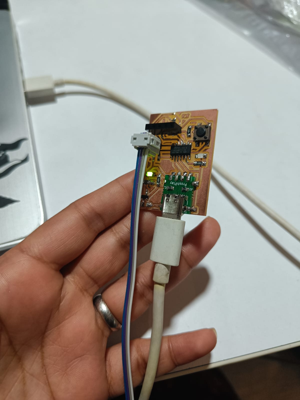
PCB WITH SAMD11C 
The microcontroller development board I designed earlier has been used for carrying out the experiments and attaining the learning outcomes for this week. The details of the board and the design are attached in the documentation of previous week. It can be found in this link .
Overview of the DHT11 Sensor
The DHT11 is a popular digital temperature and humidity sensor known for its compactness and affordability, making it a preferred choice for hobbyists and DIY projects involving environmental monitoring. This sensor is capable of measuring temperature from 0 to 50 degrees Celsius with a ±2°C accuracy and relative humidity from 20 to 80% with ±5% accuracy.
Features of DHT11 Sensor
- Voltage Requirements : Operates between 3 to 5.5 volts, making it compatible with most microcontrollers.
- Low Power Consumption : Suitable for battery-operated applications.
- Digital Output : Offers a single-wire digital interface, simplifying connections to microcontrollers.
- Calibrated : Comes factory-calibrated with digital output providing reliable readings without additional calibration by the user.
- Long-term Stability : Maintains long-term reliability and stability, with slow response time but sufficient for most applications not requiring frequent updates.
Using the DHT11 in a Circuit
To interface a DHT11 sensor with a microcontroller like the SAMD11C, you typically need a few components:
- DHT11 sensor
- SAMD11C microcontroller board
- 4.7k - 10k ohm resistor (pull-up on the data line)
- Connecting wires
- Breadboard (optional, for prototyping)
Steps to Interface DHT11 with SAMD11C
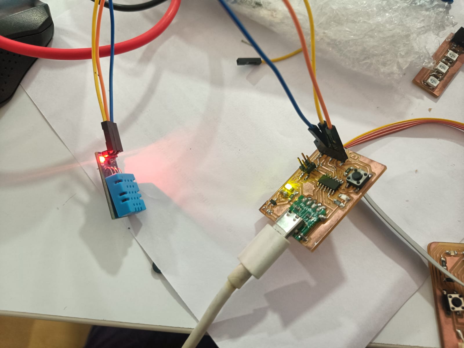
1. Circuit Connection
- VCC of DHT11 : Connect to a 3.3V or 5V output on the SAMD11C (depending on your specific setup).
- GND of DHT11 : Connect to a ground pin on the SAMD11C.
- Data Pin of DHT11 : Connect to a digital I/O pin on the SAMD11C. A typical choice might be pin PA14. Place a pull-up resistor (4.7k ohm recommended) between the data pin of DHT11 and VCC.
2. Programming Environment Setup
- Ensure that the Arduino IDE is installed and configured for the SAMD11C. This may require installing additional board packages through the Board Manager.
3. Code to Display Temperature and Humidity
Here’s a simple example code to read temperature and humidity from the DHT11 sensor and display the values on the serial monitor. This code assumes you are using the Arduino environment configured for the SAMD11C.
#include "DHT.h"

#define DHTPIN PA14     // Digital pin connected to the DHT sensor
#define DHTTYPE DHT11   // DHT 11

DHT dht(DHTPIN, DHTTYPE);

void setup() {
  SerialUSB.begin(9600);
  dht.begin();
}

void loop() {
  delay(2000); // Wait a few seconds between measurements

  // Reading temperature or humidity takes about 250 milliseconds
  float h = dht.readHumidity();          // Read humidity (percent)
  float t = dht.readTemperature();       // Read temperature as Celsius

  // Check if any reads failed and exit early (to try again).
  if (isnan(h) || isnan(t)) {
    SerialUSB.println("Failed to read from DHT sensor!");
    return;
  }

  SerialUSB.print("Humidity: ");
  SerialUSB.print(h);
  SerialUSB.print(" %\\t");
  SerialUSB.print("Temperature: ");
  SerialUSB.print(t);
  SerialUSB.println(" *C");
}
Explanation of Code
-
Libraries
: The
DHT.hlibrary is included, which facilitates communication with the DHT sensor.
- Initialization : The sensor is initialized with the type (DHT11) and the connected digital pin.
-
Reading Data
: The
readHumidity()andreadTemperature()functions are called to fetch humidity and temperature data, respectively.
- Serial Output : The data is printed to the Serial monitor, providing a simple output of temperature and humidity.
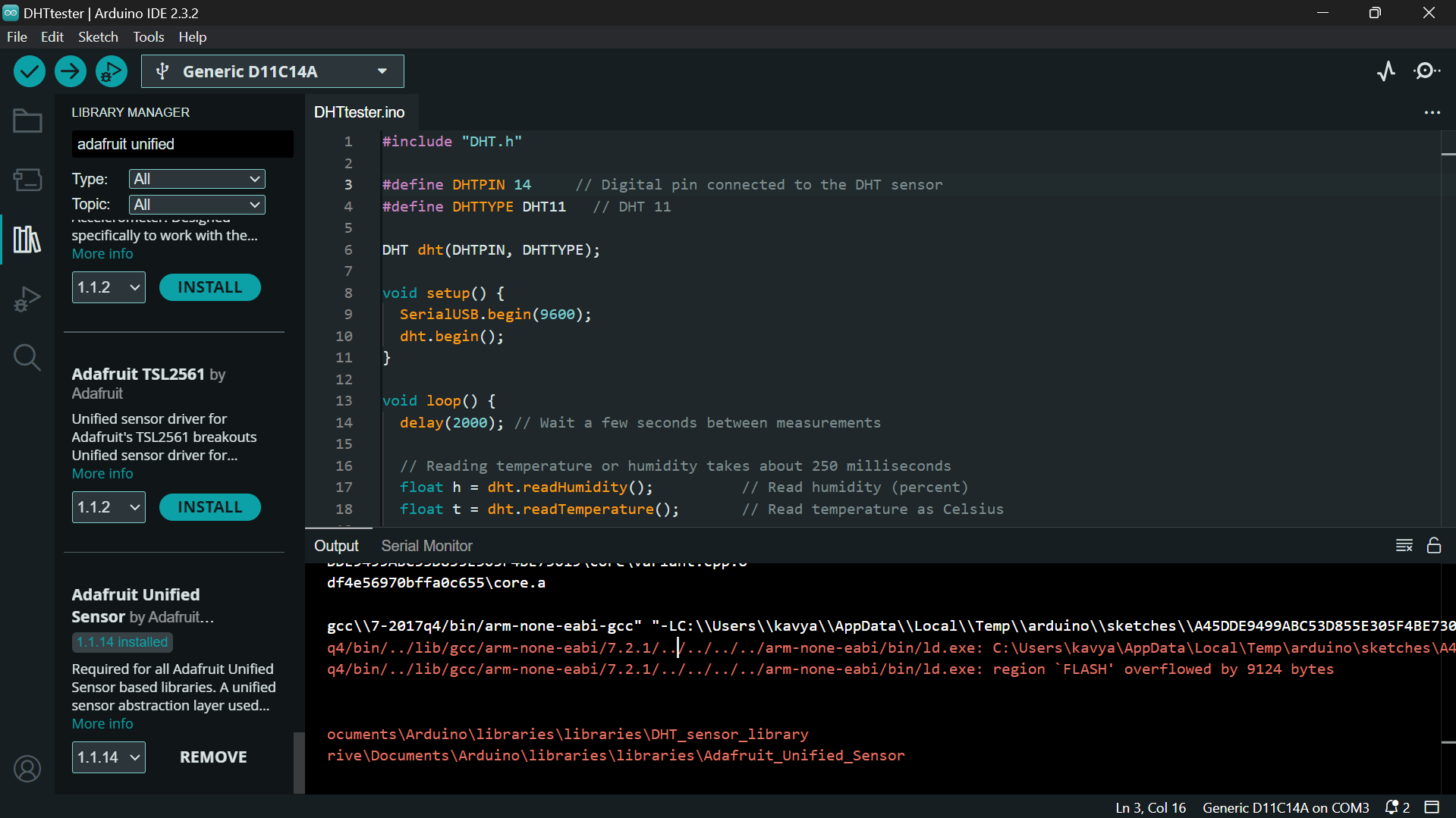
I encountered the following issue as while using the above code. My instructor helped me troubleshoot the issue and told me that it was because I was using library and it can be resolved by rewriting the code without library.
I looked for some references online to understand the logic to write a code to read temperature and humidity without using library and I have rewritten the code as follows:
// #include <Arduino.h>

// Define DHT11 data pin
#define DHT11_PIN 14

// Variables to store temperature and humidity
int humidity, temperature;

void setup() {
  Serial.begin(9600);
}

void loop() {
  uint8_t bits[5] = {0, 0, 0, 0, 0};
  uint8_t cnt = 7;
  uint8_t idx = 0;

  // Start signal
  pinMode(DHT11_PIN, OUTPUT);
  digitalWrite(DHT11_PIN, LOW);
  delay(18); // DHT11 requires at least 18 ms of low signal to detect start
  digitalWrite(DHT11_PIN, HIGH);
  delayMicroseconds(40);
  pinMode(DHT11_PIN, INPUT);

  // Wait for DHT11 response
  while(digitalRead(DHT11_PIN) == HIGH);
  while(digitalRead(DHT11_PIN) == LOW);
  while(digitalRead(DHT11_PIN) == HIGH);

  // Read the data
  for (int i = 0; i < 40; i++) {
    while(digitalRead(DHT11_PIN) == LOW);
    unsigned long duration = micros();

    while(digitalRead(DHT11_PIN) == HIGH);
    duration = micros() - duration;

    if (duration > 50) {
      bits[idx] |= (1 << cnt);
    }
    if (cnt == 0) {
      cnt = 7;    // reset bit counter
      idx++;      // next byte
    } else {
      cnt--;
    }
  }

  // Writing to variables, assuming correct transmission in bits[0] - bits[4]
  humidity = bits[0];
  temperature = bits[2];

  // Print temperature and humidity values
  Serial.print("Humidity: ");
  Serial.print(humidity);
  Serial.print("% ");
  Serial.print("Temperature: ");
  Serial.print(temperature);
  Serial.println("°C");

  delay(2000); // Delay between reads
}
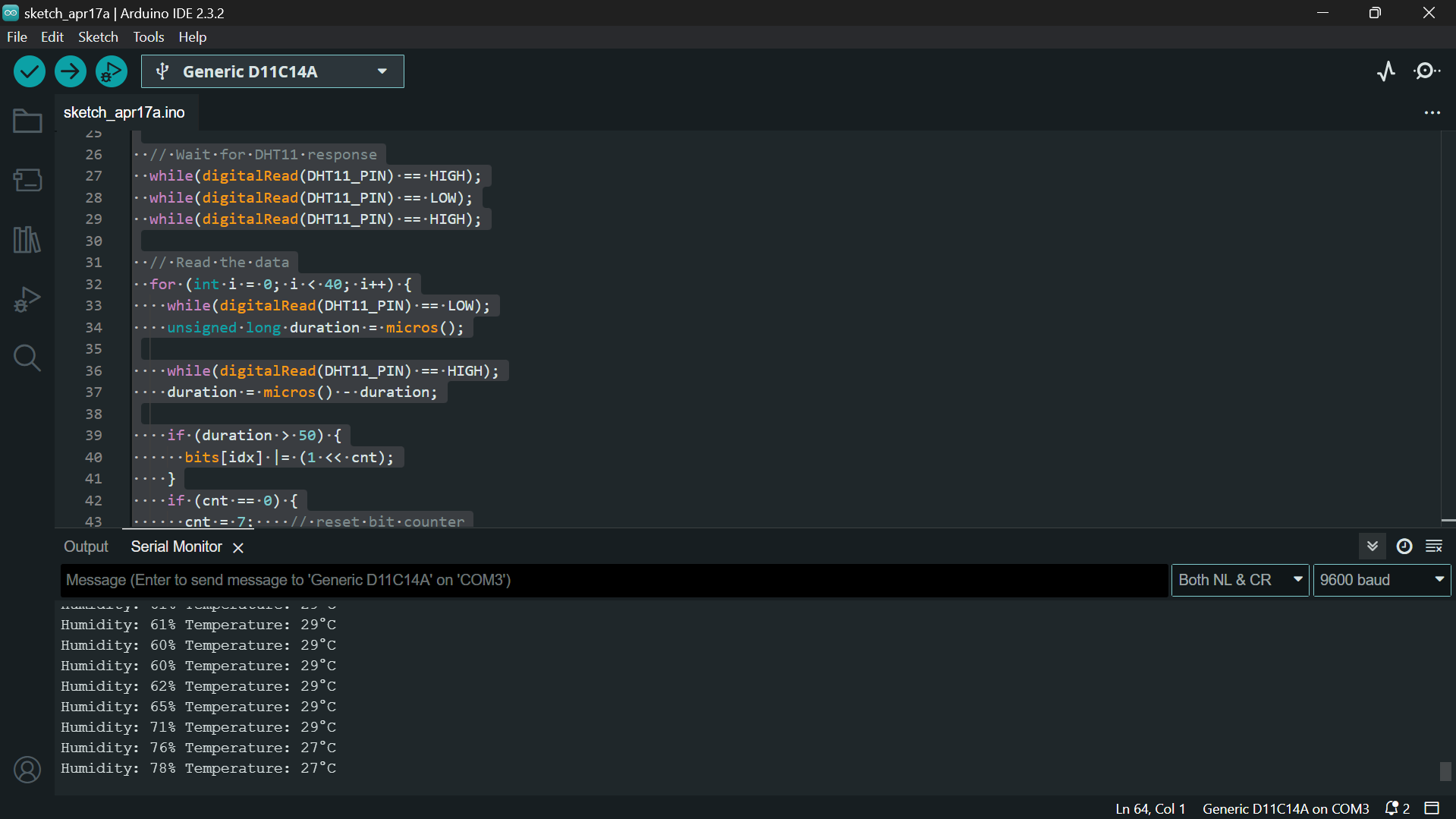
The output of the reading is as follows:
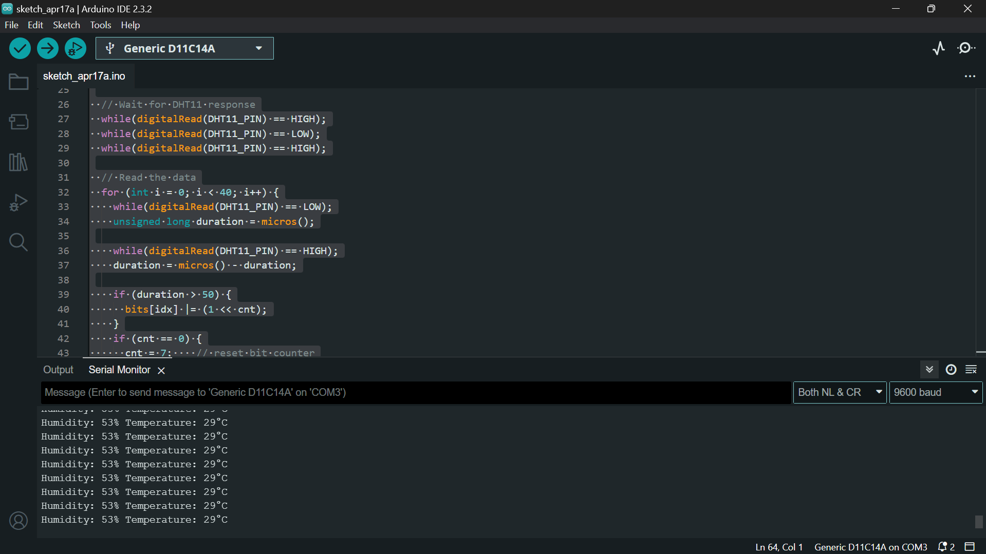
I tried testing it further by taking the sensor close to my hot water cup to check the variations in temperature and humidity. I observed that the humidity value steadily increased.
Furthermore, I am interested to explore some interesting sensor fabrication techniques that were shared by my friends.
Hence, I am referring to the following documentation: Link
Week 11 Compressed Files